
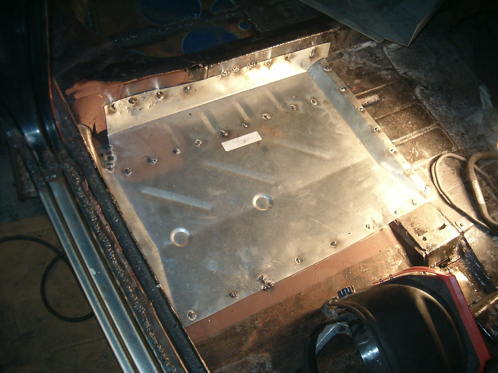
Friday evening I loaded a new spool of .023” wire into my MIG welder and finished welding in the forward patch on Ringo’s passenger side floor. With that in, I prepped the purchased patch (the backseat footwell). That included drilling a number 5/16” diameter holes for plug welds and priming the back side with Galvanizing primer. After taping off the areas on the installed floor where the plug welds will go, I primed portions of the installed floor that will be covered by the footwell patch.
With that done, I moved on to prepping pistons for rebuilding a 95HP for Ringo. Since I sold Betty, I am now without anything to trade for a running engine. Since the guy in PA never got back to me, I’d figured the deal was. So now I’m left to coming up with the most affordable method for rebuilding an engine. A friend of mine at work has all the tool required to ensure I can re-use the pistons and cylinders (size-wise) and put a nice cross-hatch on the cylinder walls. Before I can bother him, though, I need to remove the rings and clean the grooves of the pistons. I found the cylinders from the York 110HP engine are in great shape, so I’d planned on using the six pistons that came out of that engine. Four of the six pistons relinquished their rings rather easily, while piston number five took some aggressive persuading with hammer to break rust’s hold. I beat and banged on piston number six until it was damaged beyond use. This, ever after I heated it with a torch and soaked it with penetrating fluid. I’ll just use the matching one from the 95 HP engines to replace it. At that point, it was nearing midnight, so I left the fan on overnight to persuade the paint to dry and called it a day.

Saturday morning I was back out in the garage and spent some time made quick work of welding in the footwell patch. With that patch in, I did a little dance celebrating the halfway point of re-flooring. Before starting any of the driver side, however, I turned my attention to recreating a 140HP (four-carb) throttle linkage setup. As I explained in a earlier post, I’m borrowing a ’65 setup from the Jeff at the Corvair Ranch to use a template. Fortunately, Chevy used the same basic parts for the 4-carb as the standard 2-carb, and since I’ve got a couple extra 2-carb linkage assemblies, I just need to make the unique parts. Ariel’s boyfriend had offered to make them for me, but his college work got in the way. No problem, I’m a mechanical engineer – I can handle this.
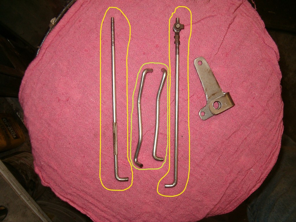
There are four new linkage rods to be made, and since I thought those the easiest to recreate I started there. The first two were straightforward (see the two circled in yellow below) – a right-angle bend to one end and a #10-32 thread cut on the opposite end. Those were finished in about an hour. Next, were the two rods circled in green. They’re not the same. Careful bending on the vise and I’m pretty happy with the results. Finally was the first of two pivot plates. I was unable to find the same thickness material, but it should be close enough for me. Since I could not damage the borrowed part, I did my best to transcribe its profile on to the sheet of metal without flattening the original. After drilling two 3/8” diameter holes at the inside radii, I used my small die-grinder with a cutoff wheel to hack out the approximate shape, and then ground it to the final profile on the bench grinder. I created the wraparound feature by rolling the metal over a 1/4” diameter drill bit. Then, with a wood spacer jammed in between the legs of the part, I drilled the 3/8” diameter hole and the two 5/32” holes. I’m planning on going up to the Corvair Ranch this Sunday, and would like to return the borrowed linkage, so I need to finish the last three parts and complete the assembly by then.
No comments:
Post a Comment